

Filters
This project started with the build of a Full Range Array, a type of speaker that gives the same power to each and every driver in the array. Corrected with EQ using FIR techniques this worked remarkably well. But as years progressed the question remained: could I make it perform even better? On the DIYaudio.com forums the tool VituixCAD from Kimmo Saunisto became a very popular tool to simulate speakers, maybe especially during the Corona period. At the start VituixCAD wasn’t equipped to be able simulate arrays but with the input of us members on the forum that soon changed, making it a viable tool to use. I was triggered by how close my real world measurements looked to those early simulations. That’s when I became interested to see how far we could go with an array like this. After countless iterations I came up with something that I thought could be worthwhile. At the time my speakers were in storage, so I could actually open them back up and add some filtering if I wanted. Long story short, I decided to give it a try and started building my filter blocks that made up the shading components.
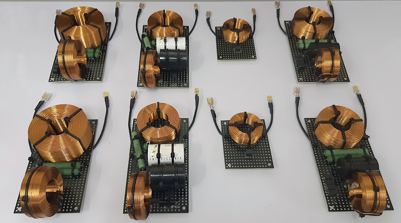
They needed to fit in the enclosure and get mounted somehow, this meant it couldn’t be too large. Air coils tend to use quite a bit of space but are superior in most cases to their iron core counterpart. The picture above does not include some boards with minor tweaks I’ve added to a couple of single speakers for even better results. The tweaks introduced here offered a more balanced vertical dispersion in comparison to an unshaded array. See this page for a more in-depth write up about that. It uses just 5 drivers full range to play the top end frequencies while more and more drivers help out the lower one goes in frequency. This makes the top end perform more precise with lower levels of comb-filtering while still being capable enough to play the lower frequencies. 
An animation showing the differences in vertical coverage between a shaded and an unshaded array.
While the unshaded array has a wider dispersion, it is more uneven and shows a much more obvious waist band effect around 600 Hz. The shaded array is more even throughout the entire frequency range and much less wild on the top end.
That resulted in having to decide to go for this modification or leave my speakers well enough alone. As I had a room renovation going on, the arrays were in storage in my garage, tempting me to open them up….
I let curiosity get the better of me and started building the filters and get them inside my enclosure. The rest is history.
Here’s the schematic for a shaded array consisting of 25x Vifa/Peerless TC9 FD18-08:
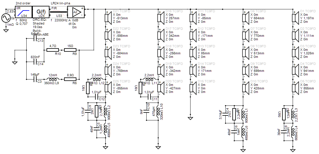 The filter components on the left form a Zobel or conjugation network, it flattens the impedance of the array. It isn’t needed as part of this shading concept but it is in use by me as part of a prior project.
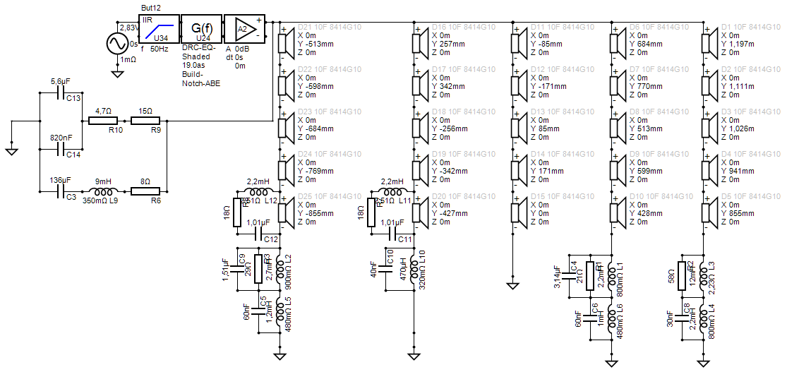
Shortly after adding these components I made the jump to another driver. See that story here. As this driver has a different impedance curve, it needed tweaks to the above schematic.
Here’s the schematic for a shaded array consisting of 25x Scan Speak 10F 8414G00:
That’s it as far as the full disclosure of my shaded array concept goes. Hope it serves you well if any of you should decide to go that route.
With this Paypal button below you can make a donation if you like the content presented here.